15W STEREO FM TRANSMITTER

| Michel P Website |
15W STEREO FM TRANSMITTER
|
|
Description
This new FM transmitter has been developped to work in standalone mode or with an external FM amplifier.
All has been integrated on one pcb: VCO, PLL, 15W RF amplifier , SWR protection, Power Regulation and the AF modulation stage.
The RF power and the PLL are controlled by the new µP board.
Frequency, AF modulation and RF Power are simultaneously diplayed on the new LCD display.
What's new in this design?
-The loop filter has been modified to ensure a -70dB spurious rejection and a locking time around 3s max..
-The 15W RF power amplifier uses: a BFG135 bipolar transistor and a RD15HVF1 LDMOS transistor.
-The power regulation acts directly on the transistors bias to adjust the power level selected through the digital board..
-The RF coupler has been modified in order to provide a constant voltage versus frequency for the SWR indication
-Finally , the SWR protection has been upgraded to react properly on impedance mismatch.
The new digital board controls the frequency, power level and locking pll parameters.
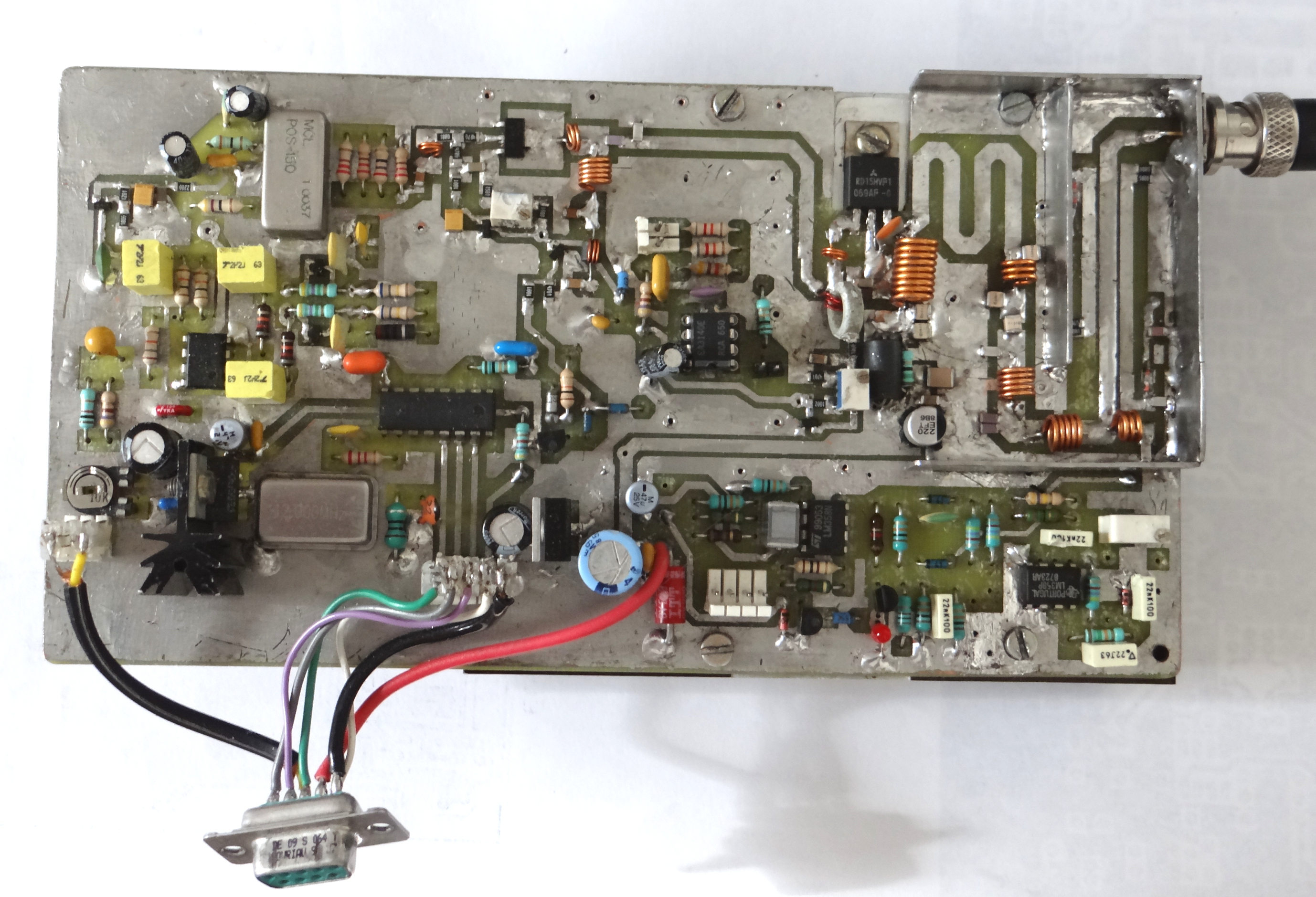
You will find below a picture of this new FM transmitter.
Exciter Specifications
Frequency Range : 87.5 MHz–108 MHz
RF Power Output : 1-15 Watts adjustable(VSWR 1.8:1 or better)
RF Output Impedance : 50 Ohms
Frequency Stability Meets ETSI specifications from 0-50
degrees C
Audio Input Impedance 22kΩ
Audio Input Level adjustable from –10 dBm to +10 dBm for
75 kHz deviation at 400 Hz
Distortion (THD + Noise) :
Less than 0.2% (30Hz-15kHz)
FM S/N Ratio (FM noise) : Better than –65dB
RF Spurious/Harmonic Products Better than –60dB
Operating Environment Temperature (0°C to 50°C)